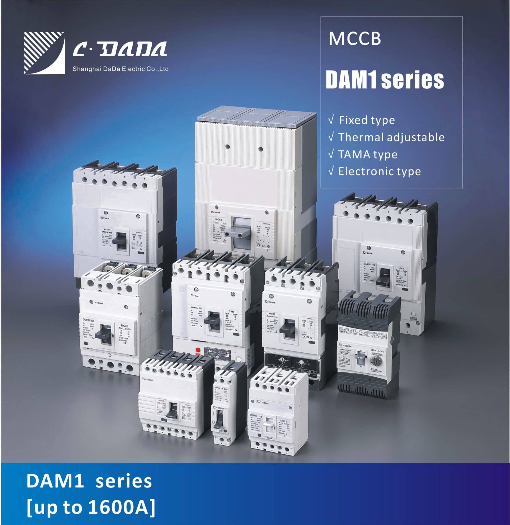
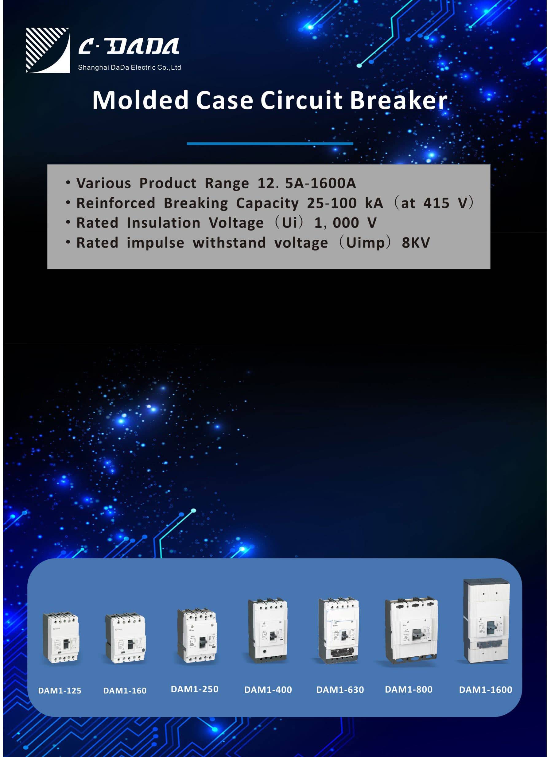
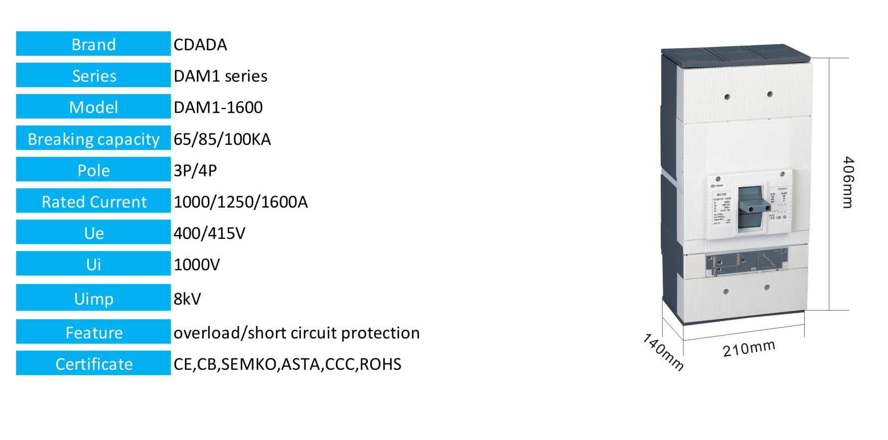
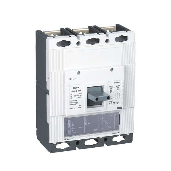
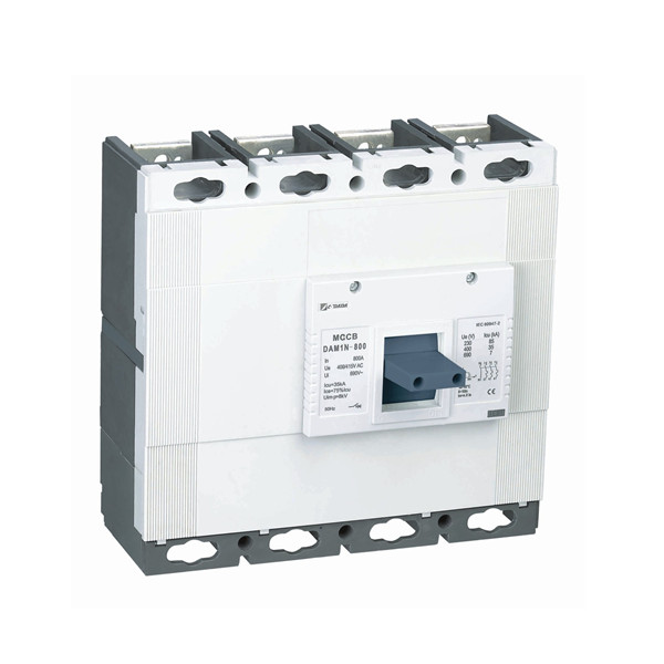
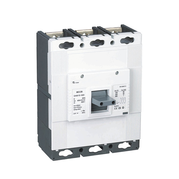
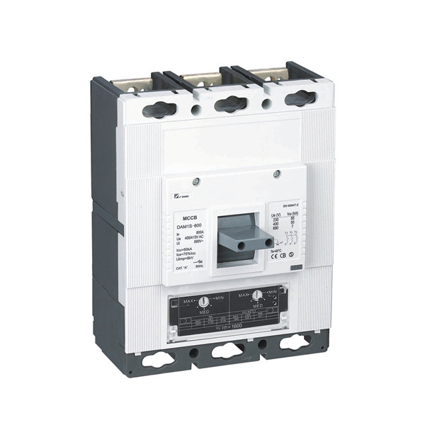
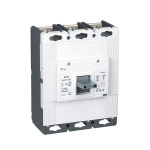
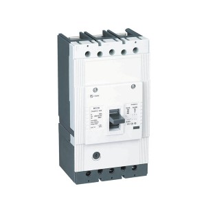
DAM1 800 MCCB Moulded Case Circuit Breaker
- Contact Us
- Address: Shanghai DaDa Electric Co.,Ltd.
- Phone: 0086-15167477792
- Email: charlotte.weng@cdada.com
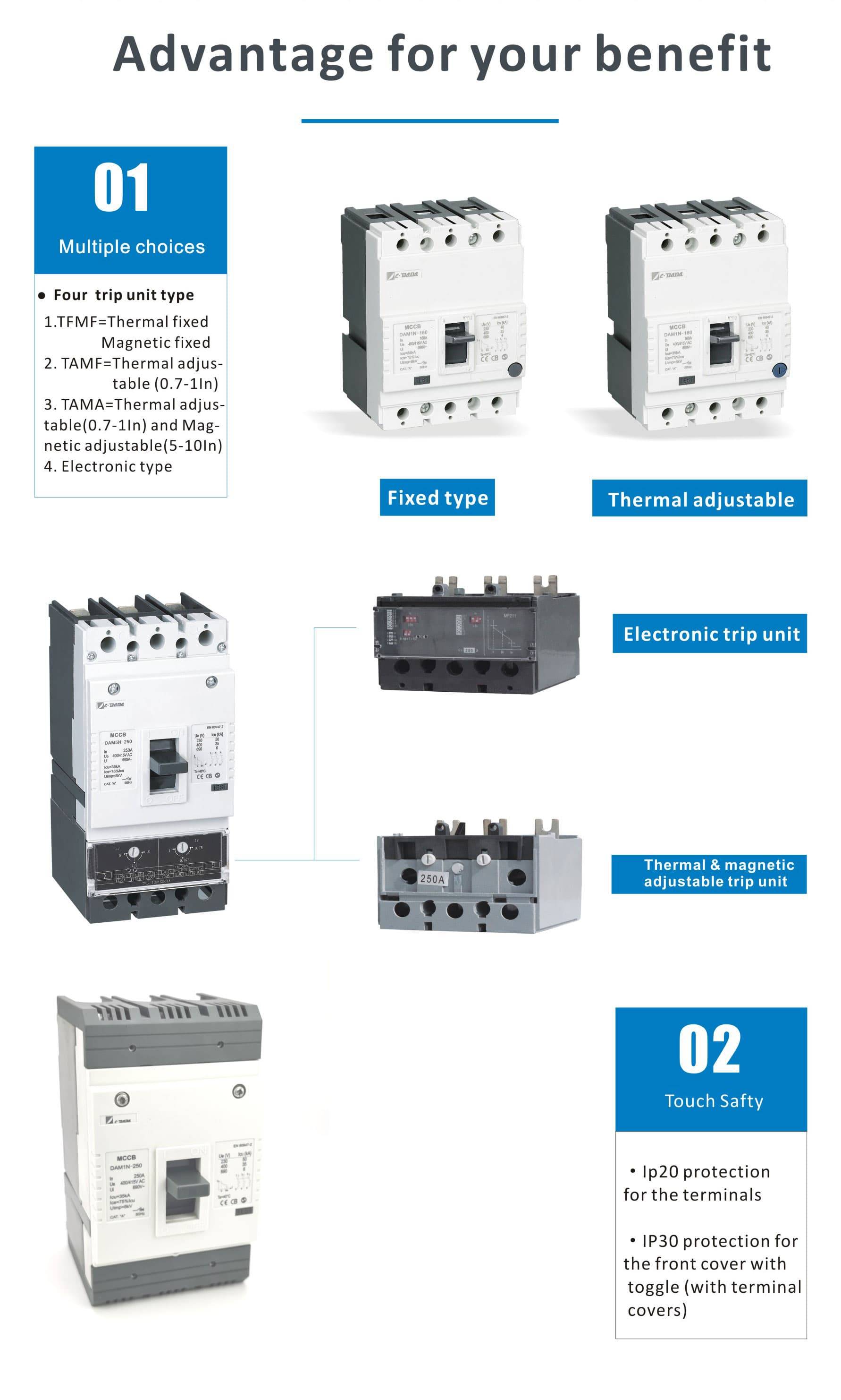
Thermal-Magnetic Circuit Breakers
Thermal protection function:(For protection under over load conditions)
Bimetal, which provides thermal protection, consists of combination of two metals with different extension coefficients under heat. When bimetal is heated, it bends towards the metal with less extension. In this way, a notch that assists opening of the breaker mechanism is released to disable the breaker. Bending speed of bimetal is in direct proportion with size of the current passing through the breaker. Because, increase of current means increase of heat. In this way, over current protection function of the breaker is fulfilled by bimetal at load currents higher than the rated current
Magnetic protection function (For protection under short circuit conditions)
Another function of the breaker is to protect the connected circuit against short circuits. Short circuit may occur as a result of contact of phases with each other or contact of phase-ground. Since a very high current shall pass through the cables in case of short circuit, system energy should be broken in a shorter time due to thermal protection. Breaker should perform instant opening to protect load it is connected to. The part fulfilling this function is a mechanical opening mechanism that operates with magnetization caused by the magnetic
area formed by the short circuit current
Advantages
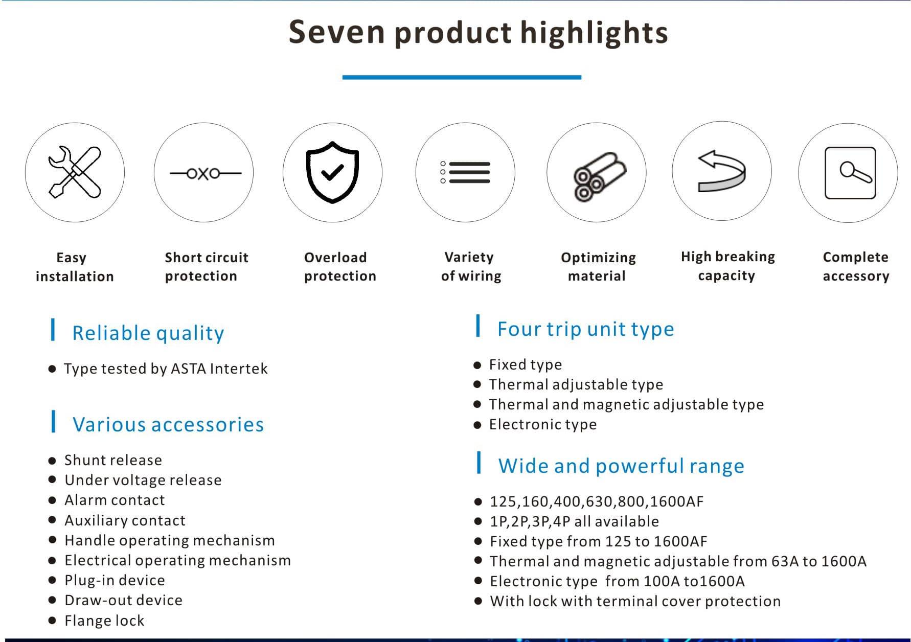
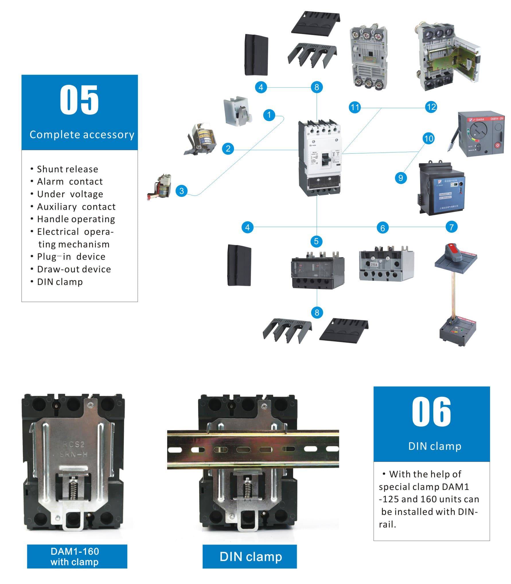
• Easy independent installation of auxiliary devices:
Alarm contact;
Auxiliary contact;
Under voltage release;
Shunt release;
Handle operating mechanism;
Electrical operating mechanism;
Plug-in device;
Draw-out device;.
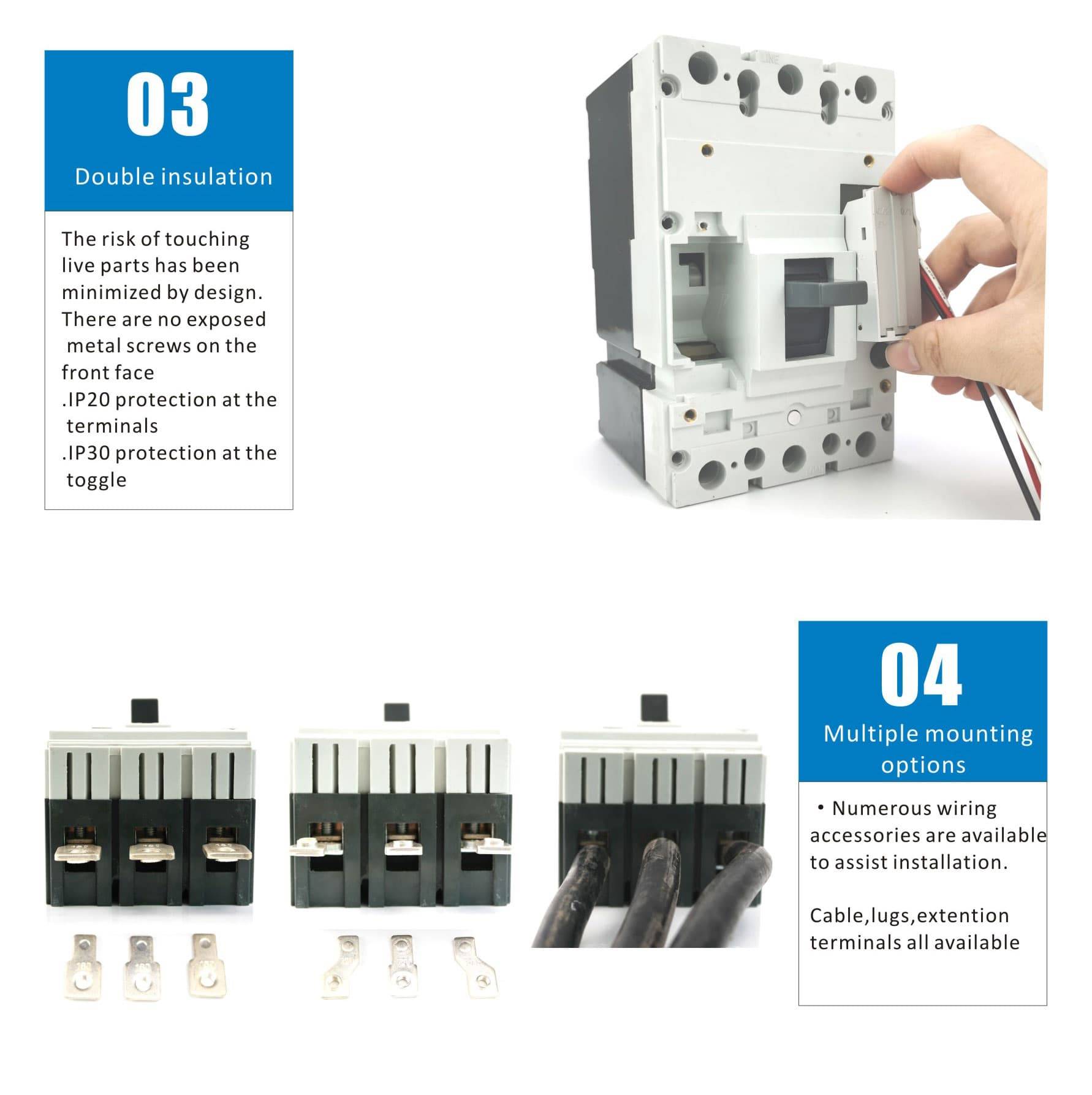
• Standard set of each circuit breaker consists of connecting busbars or cable lugs, phase separators, a set of screws and nuts for its mounting onto an installation panel.
• With the help of special clamp 125 and 160 units can be installed onto a DIN-rail.
• Weight and dimensions of these circuit breakers are by 10-20% less than that suggested by other home manufacturers. This fact provides for mounting smaller boxes and panels. Besides, small dimensions make it possible to change old circuit breakers to DAM1.
Application
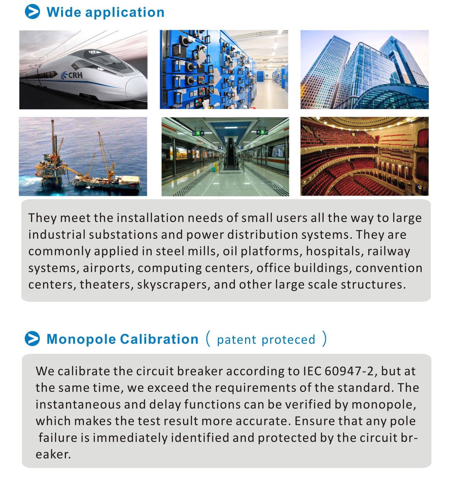
Moulded case circuit breakers are low-voltage circuit breakers. They meet the installation needs of small users all the way to large industrial substations and power distribution systems. They are commonly applied in steel mills, oil platforms, hospitals, railway systems, airports, computing centers, office buildings, convention centers, theaters, skyscrapers, and other large scale structures.
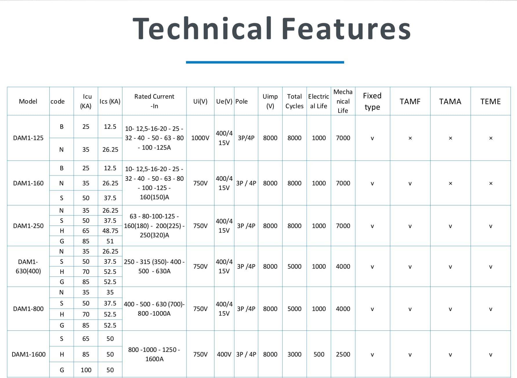
Electrical parameters of DAM1 MCCB molded case circuit breaker
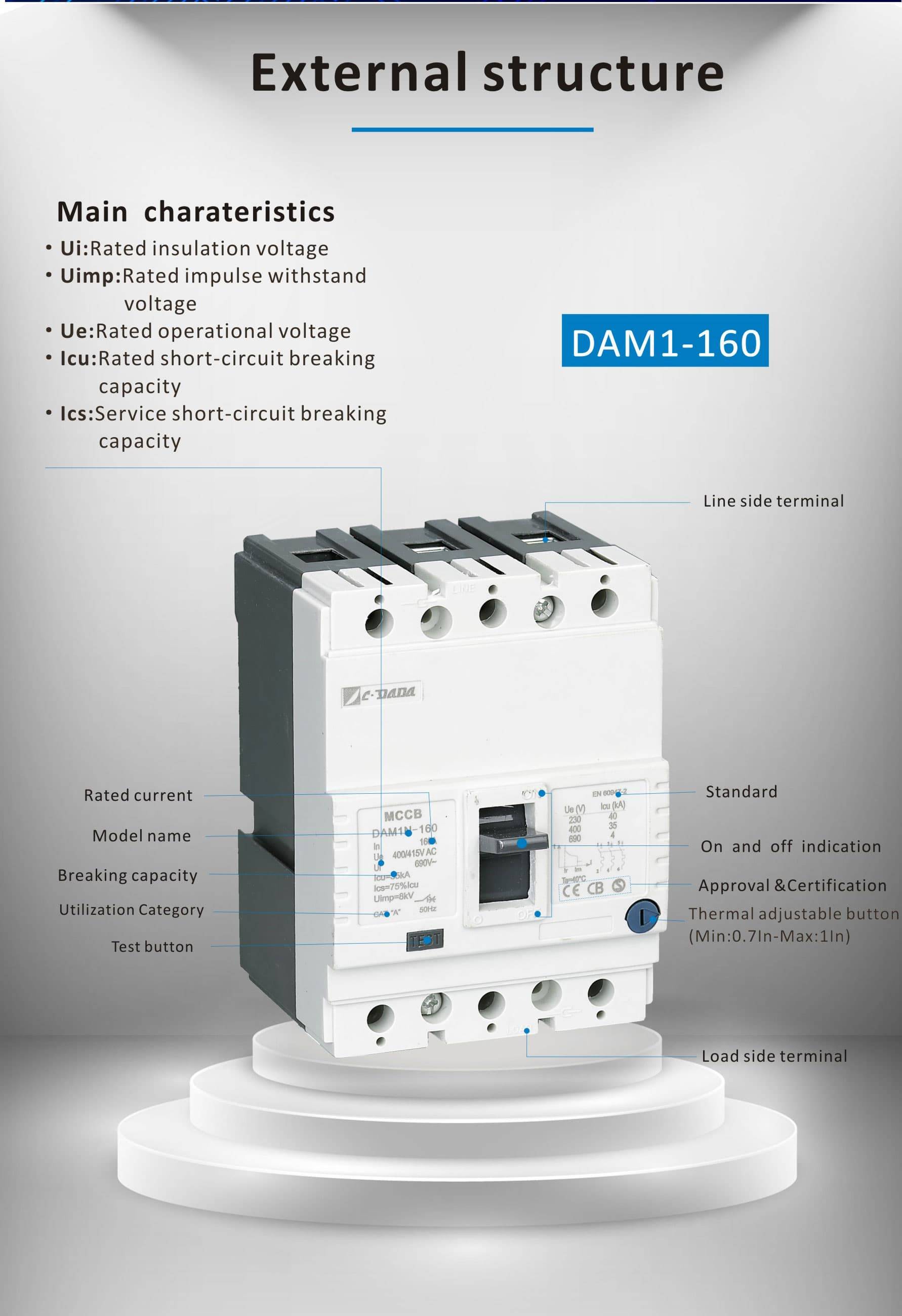
• Icu:O-t-CO test(O:Open maneuver,CO:Close-Open maneuver,t:Waiting duration)
• Ics:O-t-CO-t-CO test(O:open maneuver,CO:Close-Open maneuver,t:Waiting duration)
ON/I Position:It indicates that contacts of the breaker are closed. In this position, the breaker lever is in the top position
TRIP Position:It indicates that the breaker is opened due to any failure (over load or short circuit). In this case, breaker lever is in the middle position between ON and OFF positions. In order to take the breaker, which is in trip position, to ON position; push the breaker lever downwards as shown by the OFF sign
Breaker shall be set with “click” sound.After that, pull the lever as shown by ON sign to close the breaker
OFF/0 Position:It indicates that contacts of the breaker are open. In this way, the breaker lever is in the bottom position.
Physical parameters of MCCB molded case circuit breaker
|
Category (EN 60947-2/IEC 60947-2) |
Endurance |
|
|
|||||
|
Model |
Pole |
Dielectric Propery (V) |
lonization distance (mm) |
Total Cycles |
Electrical Life |
Mechanical Life |
Main circuit |
Auxiliary circuit |
|
DAM1-160 |
1P |
2500 |
≤30/0 |
20000 |
3000 |
17000 |
A/0 |
AC-15 |
|
DAM1-200 |
2P |
2500 |
≤30/0 |
15000 |
2500 |
12500 |
A/0 |
AC-15 |
|
DAM1-125 |
3P / 4P |
2500 |
≤30/0 |
8000 |
1000 |
7000 |
A/0 |
AC-15 |
|
DAM1-160 |
3P / 4P |
3000 |
≤30/0 |
8000 |
1000 |
7000 |
A/0 |
AC-15 |
|
DAM1-250 |
3P / 4P |
3000 |
≤30/0※ |
8000 |
1000 |
7000 |
A/B |
AC-15 |
|
DAM1-630(400) |
3P / 4P |
3000 |
≤60/0※ |
5000 |
1000 |
4000 |
A/B |
AC-15 |
|
DAM1-800 |
3P / 4P |
3000 |
≤80/0※ |
5000 |
1000 |
4000 |
A/B |
AC-15 |
|
DAM1-1600 |
3P / 4P |
3000 |
≤80/0※ |
3000 |
500 |
2500 |
A/B |
AC-15 |
