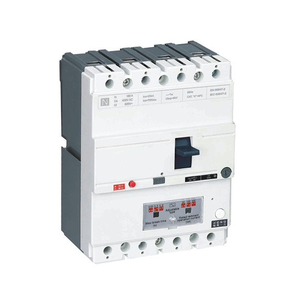
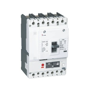
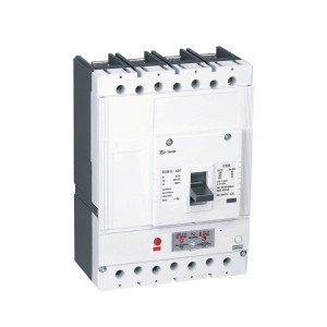
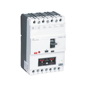
DAM1 -160L ELCB Earth Leakage protection circuit breaker1
- Contact Us
- Address: Shanghai DaDa Electric Co.,Ltd.
- Phone: 0086-15167477792
- Email: charlotte.weng@cdada.com
This circuit breaker also has the following protection:
• It provides protection for fire hazards caused by grounding fault current that cannot be detected due to overcurrent protection.
• Provide protection against the danger of increasing ground voltage due to insulation damage;
• Circuit breakers with rated residual action current not exceeding 30mA can be used for personal contact protection.
• Circuit breakers with rated current of 500A and below can also be used for infrequent start, break off during operation and overload and short circuit protection of squirrel cage motors.
DAM1L series circuit breakers can be equipped with electric accessories and mechanical accessories for various purposes, such as separately excited tripping device, auxiliary contact, alarm contact and rotating handle operating mechanism.
This series of circuit breakers are widely used in construction, transportation, tunnel, residence, etc.The delay type in this series of circuit breakers is used for branch lines
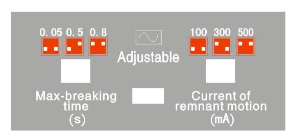
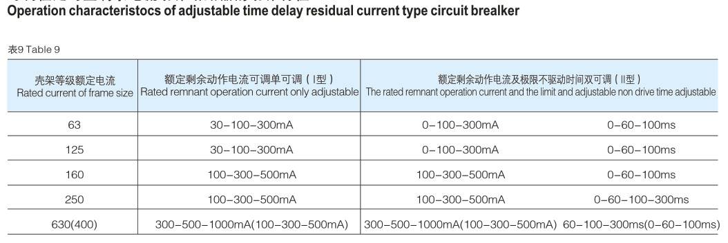
Distribution of roads;Adjustable type is used to adjust the residual action current or disconnection time on site.
Advantages
• Range:10A to 500A(AC)
• integral structure, small volume, high breaking capacity, safe and reliable.
• Adjustable magnetic setting(0.8-1times)In.
• Push to trip button provision.
• Separate main and arcing contacts
• Can be adjusted the residual action current or disconnection time according to the actual use.
• Strong anti-interference ability.
• Wide range of accessories.
The working power of the residual current protection circuit of this series of circuit breakers is supplied by the multi-phase power supply (the working power of the protection circuit of early products is supplied by the single-phase power supply)the residual current protection circuit of the device can still operate normally.When the operating power voltage of the circuit breaker’s residual current protection circuit is reduced to 50V, the circuit breaker’s residual current protection circuit can still work normally.(I coherence n=30mA)
This series of circuit breakers are classified into B type (i.e., basic breaking capacity) (Inm less than 100), S type (i.e., standard breaking capacity) and H type (i.e High score breaking capacity (Inm > 160) can be used in different situations.
The main circuit of a circuit breaker is connected in many ways:
Piston front connection
Terminal extension plate front connection
The screw connection at the rear of the piston plate
Earth-Leakage Circuit Breakers
|
Residual current circuit breaker basic parameters |
|||
|
COSφ |
Rated current of remnant motion I△n (mA)
|
Rated current of remnant no-motion I△no (mA)
|
Max-Breaking time (S) |
|
0.2 |
100,300,500 |
50,150,250 |
0.05,0.5, 0.8 |
|
Rated residual operating current(mA) |
Rated no tripping current value.I△no(mA) |
Residual current value range.(mA)0.5x(I△n+I△no)±0.2I△n |
|
30 |
15mA |
18mA-27mA |
|
100 |
50mA |
60mA-90mA |
|
300 |
150mA |
180mA-270mA |
|
500 |
250mA |
300mA-450mA |
|
1000 |
500mA |
600mA-900mA |



|
Earth-Leakage Circuit Breakers(ELCB) |
||||||||
|
Model |
DAM1-125L |
DAM1-160L |
||||||
|
Breaking Capacity Code |
B |
N |
S |
B |
N |
S |
||
|
Rated Current of Frame size- Inm (A) |
125A |
160A |
||||||
|
Rated Current-In(40,50 or 55℃) (A) |
10 – 12,5 – 16 – 20 – 25 – 32(30) – 40 – 50 – 63(60) – 80 – 100 – 125A |
10- 12,5-16-20 – 25 – 32 – 40 - 50 – 63 – 80 – 100 -125 – 160(150)A |
||||||
|
Ui (V) |
690V |
690V |
||||||
|
Ue (V) |
400V |
400/415V |
||||||
|
Number of Pole |
4P |
4P |
||||||
|
Icu (KA) |
25 |
35 |
50 |
25 |
35 |
50 |
||
|
Ics(KA) |
12.5 |
17.5 |
37.5 |
12.5 |
26.25 |
37.5 |
||
|
Icm(peak)/cos ф (KA) |
40/0.3 |
73.5/0.25 |
105/0.25 |
41/0.3 |
73.5/0.25 |
110/0.25 |
||
|
(I△m)KA/cosф |
9/0.5 |
19/0.5 |
||||||
|
Residual current threshold(mA) |
100-300-500 |
100-300-500 |
||||||
|
Time delay(ms) |
50-500-800 |
50-500-800 |
||||||
|
Uimp (V) |
10000 |
8000 |
||||||
|
Dielectric Propery (V) |
2500 |
3000 |
||||||
|
lonization distance (mm) |
≤30/0 |
≤30/0 |
||||||
|
Endurance |
Total Cycles |
8000 |
8000 |
|||||
|
ElectricalLife |
1000 |
1000 |
||||||
|
MechanicalLife |
7000 |
7000 |
||||||
|
Category (EN 60947-2/IEC 60947-2) |
Main circuit |
A/0 |
A/0 |
|||||
|
Auxiliary circuit |
AC-15 |
AC-15 |
||||||
| Under Voltage Release |
√ |
√ |
||||||
| Shunt Release |
√ |
√ |
||||||
| Auxiliary Contact |
√ |
√ |
||||||
| Alarm Contact |
√ |
√ |
||||||
| Auxiliary Contact and Alarm Contact |
√ |
√ |
||||||
| Handle Operation Mechanism |
√ |
√ |
||||||
| Electrical Operastion Mechanism |
√ |
√ |
||||||
| Terminal cover |
|
|
√ |
√ |
||||
| Phase seperator |
|
|
√ |
√ |
||||
|
|
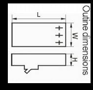
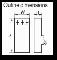
W (mm) |
3P |
- |
- |
||||
|
4P |
101 |
120 |
||||||
|
L (mm) |
3P |
- |
- |
|||||
|
4P |
155 |
120 |
||||||
|
H (mm) |
3P |
- |
- |
|||||
|
4P |
70 |
70 |
||||||
|
Weight |
Fixed version 3P/4P |
- |
- |
|||||
|
Plug-in version 3P/4P |
- |
- |
||||||
|
Draw out version 3P/4P |
- |
- |
||||||
|
Earth-Leakage Circuit Breakers(ELCB) |
||||||||||
| Model |
DAM1-250L |
DAM1-400L |
||||||||
| Breaking Capacity Code |
N |
S |
H |
G |
N |
S |
H |
G |
||
| Rated Current of Frame size- Inm (A) |
250A |
400A |
||||||||
| Rated Current-In(40,50 or 55℃) (A) |
63 – 80-100-125 – 160(180) - 200(225) – 250(320)A |
250 – 315 (350)- 400 – 500A |
||||||||
| Ui (V) |
690V |
690V |
||||||||
| Ue (V) |
400/415V |
400/415V |
||||||||
| Number of Pole |
4P |
4P |
||||||||
| Icu (KA) |
35 |
50 |
65 |
85 |
35 |
50 |
70 |
85 |
||
| Ics(KA) |
26.25 |
37.5 |
48.75 |
51 |
26.25 |
37.5 |
52.5 |
52.5 |
||
| Icm(peak)/cos ф (KA) |
77/0.25 |
114/0.25 |
143/0.2 |
178/0.2 |
70/0.25 |
110/0.25 |
154/0.2 |
187/0.2 |
||
| (I△m)KA/cosф |
12/0.3 |
19/0.5 |
||||||||
| Residual current threshold(mA) |
100-300-500 |
100-300-500 |
||||||||
| Time delay(ms) |
50-500-800 |
50-500-800 |
||||||||
| Uimp (V) |
8000 |
8000 |
||||||||
| Dielectric Propery (V) |
3000 |
3000 |
||||||||
| lonization distance (mm) |
≤30/0※ |
≤60/0※ |
||||||||
| Endurance |
Total Cycles |
8000 |
5000 |
|||||||
|
Electrical Life |
1000 |
1000 |
||||||||
|
Mechanical Life |
7000 |
4000 |
||||||||
|
Category (EN 60947-2/IEC 60947-2) |
Main circuit |
A/B |
A/B |
|||||||
|
Auxiliary circuit |
AC-15 |
AC-15 |
||||||||
| Under Voltage Release |
√ |
√ |
||||||||
| Shunt Release |
√ |
√ |
||||||||
| Auxiliary Contact |
√ |
√ |
||||||||
| Alarm Contact |
√ |
√ |
||||||||
| Auxiliary Contact and Alarm Contact |
√ |
√ |
||||||||
| Handle Operation Mechanism |
√ |
√ |
||||||||
| Electrical Operation Mechanism |
√ |
√ |
||||||||
| Terminal cover |
|
|
√ |
√ |
||||||
| Phase seperator |
|
|
√ |
√ |
||||||
|
|
W (mm) |
3P |
- |
- |
||||||
|
4P |
140 |
184 |
||||||||
|
L (mm) |
3P |
- |
- |
|||||||
|
4P |
210 |
254 |
||||||||
|
H (mm) |
3P |
- |
- |
|||||||
|
4P |
103.5 |
103.5 |
||||||||
|
Weight |
Fixed version 3P/4P |
- |
41.5/5.5 |
5.1/7.1 |
||||||
|
Plug-in version 3P/4P |
- |
4.6/6 |
6.5/8.5 |
|||||||
|
Draw out version 3P/4P |
- |
5/6.4 |
6.5/8.7 |
|||||||
• Icu:O-t-CO test(O:Open maneuver,CO:Close-Open maneuver,t:Waiting duration)
• Ics:O-t-CO-t-CO test(O:open maneuver,CO:Close-Open maneuver,t:Waiting duration)


